.jpg)
Clock/Time Table/Reminder System for Classrooms
Done at SSNCE, 2018
Introduction
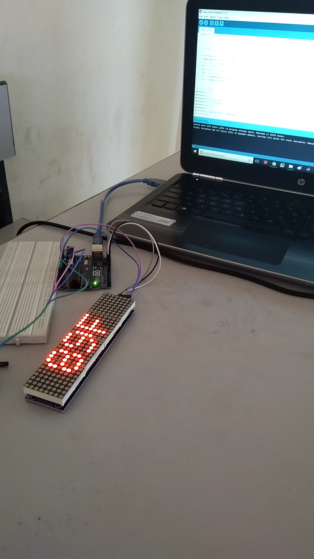
Clock/Time Table/Reminder System is a device that displays the time, temperature (in Celsius), date, day and month. This device is made to be used in classrooms. The real-time clock (RTC) module used in this project is a computer clock (most often in the form of an integrated circuit) that keeps track of the current time. The module comprises of a DS3231 IC, an EPROM to store memory and Lithium button battery to provide power to the module. This handy module keeps accurate time using a tiny coin-cell, and is very simple to connect to your Arduino project. A driver library allows your program to easily set or read the time and date. We control the four 8×8 LED Matrix using the MAX7219 driver and the Arduino board. The IC is capable of driving 64 individual LEDs while using only 3 wires for communication with the Arduino, and what’s more we can daisy chain multiple drivers and matrixes and still use the same 3 wires.
Code for the project is found here.
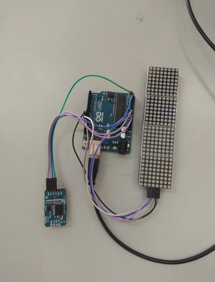
Connections
Operation
The DS3231 is a low-cost, extremely accurate I2C real time clock (RTC) with an integrated temperature compensated crystal oscillator (TCXO) and crystal. Also, it has automatic compensation for leap-years (until the year 2100) and for months with fewer than 31 days. It can be set with the required time with ease. The module can work on either 3.3 or 5 V. In this particular project we use a 3V Li coin battery. To display the temperature (in degree Celsius), time in hours and minutes, the day of the week and the date with the month we make use of the cascaded 8x8 LED dot matrix module. We use four such modules, this makes up the hardware. The MD_DS3231 header file helps in read write and control functions. The RTC is initially set to the required date, day and time. The RTC outputs a byte for each of the variables, the MD Maxx72xx library displays “char”. So we must convert the bytes to chars. This is done with the help of the ASCII codes. We adapt the “Print Text” example function to of the MAX72xx library display the clock data on the screen. Using simple if-else-if cases we can decide the information to be displayed and for a particular time duration. Once the Arduino board is powered up, the LED matrix module displays clock data as per the code. The RTC will contain the previous settings until the battery is removed.