.jpg)
Rubik’s Cube Solver Bot
Done at SSNCE, 2019
Introduction
The project is a Rubik’s Cube Solver Bot whose primary objective is to solve the Rubik’s Cube in the least number of moves. Stepper motors are used to control the rotation of grippers which rotate the faces of the cube during the cube solving process. The Bot utilizes an Arduino UNO microcontroller to control and coordinate the rotation of the stepper motors.
Code for the project is found here.
Components
(1) Stepper Motors
NEMA 17 and NEMA 23 are the two varieties of stepper motors used. Two NEMA 23 motors and four NEMA 17 motors were used for the Bot. The NEMA 17 can be used as a unipolar or bipolar stepper motor and has a 1.8° step angle (200 steps/revolution). Each phase draws 1.2 A at 4 V, allowing for a holding torque of 3.2 kg-cm. Since the torque required to rotate the face of the Rubik’s cube is low, NEMA 17 was used. Four of these are used to manipulate the four grippers which in turn rotate the faces of the cube as required. The NEMA 23 bipolar stepper motor has a 1.8° step angle (200 steps/revolution). Each phase draws 2.8 A at 3.2 V, allowing for a holding torque of 19 kg-cm. NEMA 23, due to its higher torque, was used to move the platforms lodging the NEMA 17 motors.
(2) Arduino UNO
Arduino Uno was the microcontroller that was used for the bot due to its high functionality in interfacing, synchronizing and controlling the six stepper motors. The Arduino reads the solution string from the Kociemba algorithm’s output. The solution string indicates the specific moves required to solve the cube. Each move in the string is extracted and carried out by invoking its corresponding function which is coded as a program in C language using the Arduino IDE. These invoked functions enable the Arduino to send appropriate control signals to the stepper motor to solve the cube.
(3) Motor Driver
Motor Drivers are current amplifiers. They act as a bridge between the controller and the motor in a motor drive. For efficient functioning of the stepper motors, various stepper motor drivers were experimented. L293D and DRV6625 were initially tested, but its functionalities and features were limited and its design proved to be inefficient in the long run. Hence, TB6600 was preferred because of its high voltage and current capacities and its ability to prevent back EMF which is a vital precaution parameter when stepper motors are used. It also has overheat, over current and short circuit protection.
(4) Switched Mode Power Supply
The two types of stepper motors used namely NEMA 17 and NEMA 23 have different specifications each. The NEMA 17 stepper motor draws 1.2 A at 4V while NEMA 23 stepper motor draws 2.8 A at 3.2 V for each phase. Hence, a power supply with high current capability was required. To give the necessary torque required for NEMA 17 to rotate the face of the Rubik’s cube and for NEMA 23 to move the platform in turn displacing two NEMA 17 stepper motors, high voltage is required. So we chose the Switched Mode Power Supply (SMPS) for the Rubik’s Cube Solver Bot. The NEMA 17 stepper motors used the 12V, 10A SMPS and the NEMA 23 steppers motors utilized the 24V, 10A SMPS.
(5) Mechanical Assembly
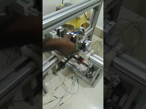
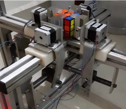
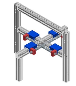
The frame of the Bot was fabricated using aluminium as it is a lightweight material and so it makes the structure portable. The four grippers, used to rotate the faces of the cube, are manipulated using four NEMA 17 stepper motors which are mounted on a platform. These platforms are placed on aluminium rails and are connected to two NEMA 23 stepper motors which aid in its back and forth movement. A NEMA 23 stepper motor, which is positioned below the rails, helps with the motion of two NEMA 17 stepper motors. The grippers were made using acrylic sheets and are attached to the shaft of the corresponding stepper motors.
Working
Input Current State
The current state of the Rubik’s Cube ie. the information of the colours on the faces of the unsolved cube are inputted to the computer. The code used for colour recognition is given here.
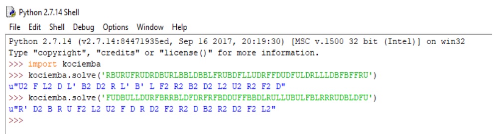
Kociemba’s Algorithm
Kociemba’s Algorithm is applied to the input on python and the optimum solution to solve the cube is computed and it is outputted in the form of a string data type. The output string is in the form of the “Singmaster notation”, which was developed by David Singmaster. The letters L, R, F, B, U, and D indicate a clockwise quarter-turn of the left, right, front, back, up, and down face respectively. Half turns are indicated by appending a 2. A counterclockwise quarter turn is indicated by appending a prime symbol ( ′ ).
Connecting the Stepper Motors to the Arduino UNO via TB6600 Driver
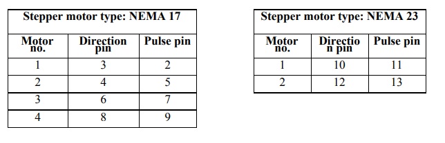
The stepper motors are controlled by the Arduino UNO via the motor driver, TB6600. The three main input signals to be given to the motor driver are direction signal, pulse signal and the 5V input which are from the Arduino UNO. The pin connections from Arduino UNO to the driver are given in the table below. The power supply connections are given to the V+ and ground pins. The motor is connected to the driver using four wires coloured red, blue, black and green to the pins A+, A-, B+ and B-.
Programming the Arduino UNO
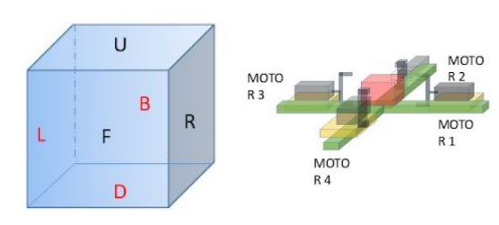
The program in the Arduino UNO reads the output string and sends control signals to the stepper motor drivers. The identification of the stepper motors and the faces of the Rubik’s cube are shown in the figure below.
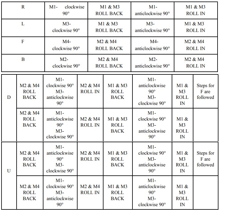
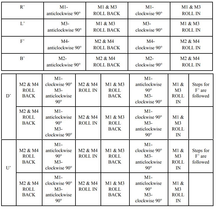
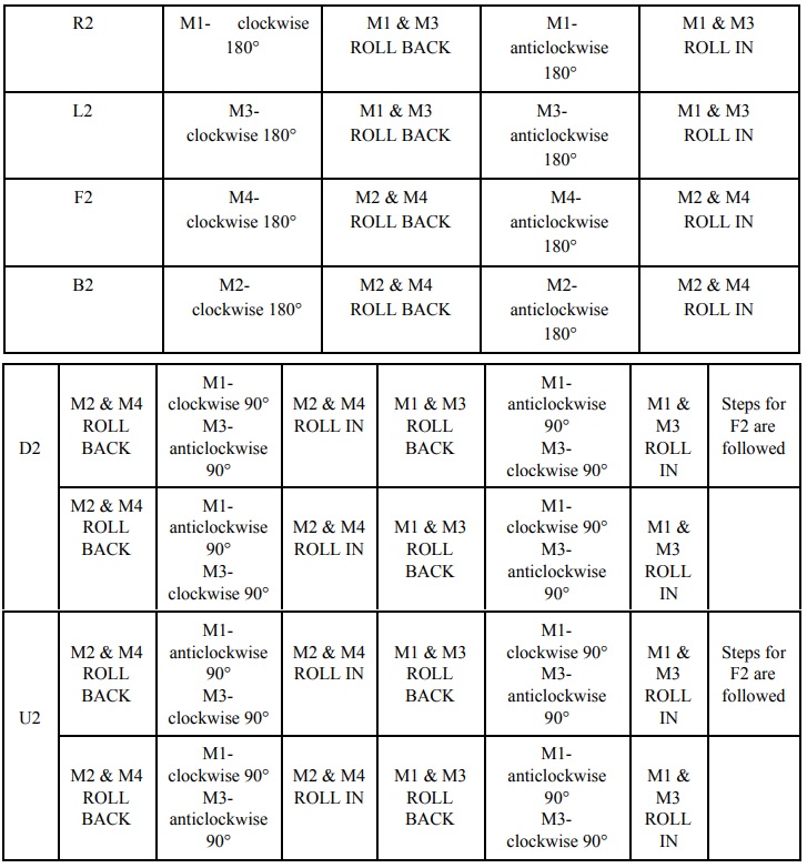
The sequence followed by the different stepper motors for each of the movements required to the solve the Rubik’s cube namely R, L, F, B, D, U, R2, L2, F2, B2, D2, U2, R’, L’, F’, B’, D’ and U’ in the Singmaster Notation are given in the tables below. “ROLL IN” means that the mentioned stepper motors move towards the Rubik’s cube and the grippers connected to them hold the cube. Similarly, “ROLL OUT” means that the corresponding stepper motors leave the grip of the Rubik’s cube and move backwards. The “ROLL IN” and “ROLL OUT” methods for the two pairs of NEMA 17 stepper motors are performed with the help of two NEMA 23 stepper motors present directly below the rails.
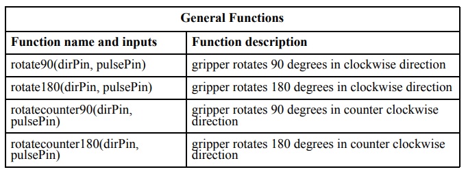
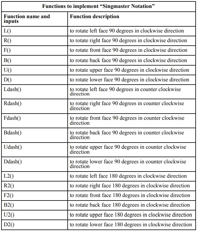
The functions coded in the program which are invoked correspondingly to solve the Rubik’s cube are shown in the tables below. They also include the inputs that are required to be provided and action performed when the function is called.
The control signals are sent sequentially to a particular motor driver which rotates the specific stepper motor which in turn rotates the face of the cube. The control signals are consecutively sent to the motor drivers with a small time delay to ensure proper rotation of faces of the cube. After all the rotation moves are performed on the cube by the grippers, the Rubik’s cube is completely solved.
Watch the Bot in action!!